
Vacuum lock syringe
Medical Supplies
Instructions for Use
-
- Do not use if the pouch is damaged.
- Do not use after the expiration date.
-
- 1. Open the package and remove the syringe.
- 2. Fill the syringe with fluid and remove any air bubbles.
- 3. Connect the syringe to the appropriate device, then gently inject
the fluid into the blood vessel to enhance vein visibility. - 4. When extracting bodily fluids, pull the plunger while using the yellow snap ring
located at the end of the barrel.
Engage the snap ring with the locking section inside the plunger to secure it in place.
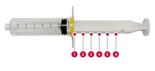
The locking mechanism allows fixation at six incremental levels (Levels 1–6), preventing
the plunger from being pulled back or slipping downward during suction.
-
- This product is a single-use medical device. Do not reuse or re-sterilize.
- Store and handle the product to avoid exposure to moisture, heat, or contamination.
Appearance Description

-
Barrel
Cylindrical in shape with graduated volume markings clearly displayed on the outer surface
-
Plunger Stopper
Attached to the plunger rod and designed to fit tightly inside the barrel,
providing effective suction and compression -
Plunger Rod
It is used to aspirate and dispense fluids by pushing or pulling.
Locking pins protrude from the plunger rod at regular intervals and
engage with the snap ring to prevent unintended forward movement of the rod. -
Snap Ring
Located on the syringe barrel, the snap ring engages with the plunger
locking pins to secure the plunger at fixed positions.
-
Stage 1
Plunger rod position No. 1 engages with the snap ring to activate the lock.
-
Stage 2
Plunger rod position No. 2 engages with the snap ring to activate the lock.
-
Stage 3
Plunger rod position No. 3 engages with the snap ring to activate the lock.
-
Stage 4
Plunger rod position No. 4 engages with the snap ring to activate the lock.
-
Stage 5
Plunger rod position No. 5 engages with the snap ring to activate the lock.
-
Stage 6
Plunger rod position No. 6 engages with the snap ring to activate the lock.